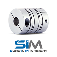
Coupling Servo Motor 
|
Dimensions / Performanc
Set-screw
| Model |
CAD |
Size (±0.3mm) |
Screw |
Rated
Torque
(N·m) |
Max.
Torque
(N·m) |
Max.
rpm
(min-1) |
Moment
of
Inertia
(kg·m2) |
Static
Torsional
Stiffness
(N·m/rad) |
Mass
(g) |
Permissible Misalignment |
| D |
L |
L1 |
F |
Size |
Fastening
Torque
(N·m) |
Angular
(˚) |
Parallel
(mm) |
End-
play
(mm) |
| SRB-8 |
 |
7.9 |
14 |
3.5 |
1.7 |
M2 |
0.3 |
0.1 |
0.2 |
50,000 |
1.2 x 10⁻⁸ |
16 |
1.5 |
2.5 |
0.1 |
±0.2 |
| SRB-12 |
 |
12.7 |
18 |
4.5 |
2.2 |
M2.5 |
0.5 |
0.2 |
0.4 |
40,000 |
1.1×10⁻⁷ |
40 |
4.4 |
2.5 |
0.1 |
±0.3 |
| SRB-16 |
 |
16 |
18.5 |
4.7 |
2.3 |
M3 |
0.7 |
0.4 |
0.8 |
30,000 |
2.8×10⁻⁷ |
75 |
7.2 |
2.5 |
0.15 |
±0.3 |
| SRB-19 |
 |
19.1 |
22 |
6 |
2.9 |
M3 |
0.7 |
0.6 |
1.2 |
24,000 |
6.4×10⁻⁷ |
150 |
12 |
2.5 |
0.15 |
±0.3 |
| SRB-22 |
 |
22.2 |
25 |
6.5 |
3.2 |
M4 |
1.7 |
1 |
2 |
20,000 |
1.4×10⁻⁶ |
200 |
17.4 |
2.5 |
0.15 |
±0.4 |
| SRB-26 |
 |
26.2 |
30 |
7.7 |
3.4 |
M4 |
1.7 |
2 |
4 |
18,000 |
3.1×10⁻⁶ |
340 |
29.2 |
2.5 |
0.2 |
±0.4 |
| SRB-32 |
 |
31.8 |
39 |
9.4 |
4.7 |
M5 |
4 |
3.8 |
7.6 |
18,000 |
9.4×10⁻⁶ |
450 |
56.8 |
2.5 |
0.2 |
±0.4 |
| SRB-39 |
 |
39 |
56 |
16 |
5.9 |
M5 |
4 |
7 |
14 |
12,000 |
2.8×10⁻⁵ |
640 |
124 |
2.5 |
0.25 |
±0.4 |
| SRB-49 |
 |
49 |
70 |
19.8 |
9.4 |
M6 |
7 |
15 |
30 |
10,000 |
1.0×10⁻⁴ |
1,500 |
280 |
2.5 |
0.25 |
±0.5 |
| SRB-60 |
 |
60 |
88 |
19 |
9 |
M8 |
15 |
30 |
60 |
8,500 |
2.7×10⁻⁴ |
2,500 |
500 |
2.5 |
0.3 |
±0.5 |
- The Moment of Inertia and Mass values are based on products with max. Inner diameter.
- The number of screw for SRB-8 is 1pc and shaft-insertion depth is up to L1. (No relief structure).
- Max. torque/rated torque is the value regarding to a coupling’s self-durability and is not related to slip-torque between the coupling bore and the shaft. (Set-screw type is usually less durable than other clamping method, thus please consider it has a complementary option e.g. keyway along with.)
Side-clamp

| Model |
CAD |
Size (±0.3mm) |
Screw |
Rated
Torque
(N·m) |
Max.
Torque
(N·m) |
Max.
rpm
(min-1) |
Moment
of
Inertia
(kg·m2) |
Static
Torsional
Stiffness
(N·m/rad) |
Mass
(g) |
Permissible Misalignment |
| D |
L |
L1 |
F |
Size |
Fastening
Torque
(N·m) |
Angular
(˚) |
Parallel
(mm) |
End-
play
(mm) |
| SRB-12C |
 |
12.7 |
19 |
5 |
2.5 |
M2 |
0.5 |
0.2 |
0.4 |
35,000 |
1.1×10⁻⁷ |
40 |
4.4 |
2.5 |
0.1 |
±0.3 |
| SRB-16C |
 |
16 |
21.5 |
6.1 |
3 |
M2.6 |
1 |
0.4 |
0.8 |
27,000 |
3.1×10⁻⁷ |
75 |
8.2 |
2.5 |
0.15 |
±0.3 |
| SRB-19C |
 |
19.1 |
23 |
6.2 |
3.1 |
M2.6 |
1 |
0.6 |
1.2 |
20,000 |
6.4×10⁻⁷ |
150 |
12 |
2.5 |
0.15 |
±0.3 |
| SRB-22C |
 |
22.2 |
26.5 |
7.2 |
3.6 |
M3 |
1.7 |
1 |
2 |
18,000 |
1.4×10⁻⁶ |
200 |
17.9 |
2.5 |
0.15 |
±0.4 |
| SRB-26C |
 |
26.2 |
31.5 |
7.5 |
3.7 |
M3 |
1.7 |
2 |
4 |
17,000 |
3.2×10⁻⁶ |
340 |
29.9 |
2.5 |
0.2 |
±0.4 |
| SRBA-32C |
 |
31.8 |
39 |
9.4 |
4.7 |
M4 |
3.5 |
3.8 |
7.6 |
14,000 |
8.6×10⁻⁶ |
450 |
54.9 |
2.5 |
0.2 |
±0.4 |
| SRBB-32C |
 |
31.8 |
44 |
9.4 |
4.7 |
M4 |
3.5 |
3.8 |
7.6 |
14,000 |
1.0×10⁻⁵ |
450 |
62.3 |
2.5 |
0.2 |
±0.4 |
| SRBA-39C |
 |
39 |
43 |
10.7 |
5.3 |
M5 |
8 |
7 |
14 |
10,000 |
2.1×10⁻⁵ |
640 |
87.8 |
2.5 |
0.25 |
±0.4 |
| SRBB-39C |
 |
39 |
56 |
12 |
5.5 |
M5 |
8 |
7 |
14 |
10,000 |
2.8×10⁻⁵ |
640 |
117 |
2.5 |
0.25 |
±0.4 |
| SRBA-49C |
 |
49 |
63.5 |
15.1 |
7.5 |
M6 |
13 |
15 |
30 |
10,000 |
8.4×10⁻⁵ |
1,500 |
236 |
2.5 |
0.25 |
±0.5 |
| SRBB-49C |
 |
49 |
70 |
14.5 |
7.2 |
M6 |
13 |
15 |
30 |
8,400 |
1.0×10⁻⁴ |
1,500 |
258 |
2.5 |
0.25 |
±0.5 |
| SRBA-60C |
 |
60 |
76.2 |
19 |
9.4 |
M8 |
30 |
30 |
60 |
7,000 |
2.2×10⁻⁴ |
2,500 |
407 |
2.5 |
0.25 |
±0.5 |
| SRBB-60C |
 |
60 |
88 |
19 |
9.4 |
M8 |
30 |
30 |
60 |
7,000 |
2.6×10⁻⁴ |
2,500 |
483 |
2.5 |
0.25 |
±0.5 |
- The Moment of Inertia and Mass values are based on products with max. Inner diameter.
- Max. torque/rated torque is the value regarding to a coupling’s self-durability and is not related to slip-torque between the coupling bore and the shaft.
Standard Inner Diameter (ID)
| Model |
Standard Inner Diameter (d1, d2) (mm) |
| 2 |
3 |
4 |
5 |
6 |
6.35 |
8 |
9.525 |
10 |
11 |
12 |
14 |
15 |
16 |
18 |
19 |
20 |
22 |
24 |
25 |
| SRB-8□ |
● |
● |
|
|
|
|
|
|
|
|
|
|
|
|
|
|
|
|
|
|
| SRB-12□ |
|
● |
● |
● |
|
|
|
|
|
|
|
|
|
|
|
|
|
|
|
|
| SRB-16□ |
|
● |
● |
● |
● |
|
|
|
|
|
|
|
|
|
|
|
|
|
|
|
| SRB-19□ |
|
|
● |
● |
● |
● |
● |
|
|
|
|
|
|
|
|
|
|
|
|
|
| SRB-22□ |
|
|
|
● |
● |
● |
● |
● |
● |
|
|
|
|
|
|
|
|
|
|
|
| SRB-26□ |
|
|
|
● |
● |
● |
● |
● |
● |
● |
● |
|
|
|
|
|
|
|
|
|
| SRB□-32□ |
|
|
|
|
|
|
● |
● |
● |
● |
● |
● |
● |
|
|
|
|
|
|
|
| SRB□-39□ |
|
|
|
|
|
|
|
|
● |
● |
● |
● |
● |
● |
● |
● |
|
|
|
|
| SRB□-49□ |
|
|
|
|
|
|
|
|
|
|
● |
● |
● |
● |
● |
● |
● |
|
|
|
| SRB□-60□ |
|
|
|
|
|
|
|
|
|
|
|
|
● |
● |
● |
● |
● |
● |
● |
● |
- The recommended shaft tolerance is h7.
- Custom process (e.g. non-standard Inner diameter, special tolerance etc.) is also available upon a special request in prior to order placement.
- Keyway is available. (Optional)
Slip Torque
- The below table shows the actual permissible torque values when the slip torque value is lower than the coupling’s max. torque value.
- If the slip torque value is lower than the coupling’s max. torque value, please check and compare between the slip torque in the below table and the operating torque value of the connected motor. It is safer to size up the coupling or use a key/keyway when the slip torque value is lower than the motor’s operating torque.
- The below slip torque values may be subject to change according to different testing conditions. (e.g. shaft tolerance, surface roughness, surface treatment or acceleration/deceleration of driving shafts). On the other hand, the values could be affected when a different kind of fastening screw is used (body material or surface treatment). Therefore, we recommend you test under the same conditions before mounting.
| Model |
Max.
Torque
(N·m) |
Slip Torque (N·m) by Inner Diameter (d1, d2) |
| 5 |
6 |
6.35 |
8 |
9.525 |
10 |
11 |
12 |
14 |
15 |
16 |
18 |
19 |
| SRB-26C |
4 |
2.2 |
2.8 |
2.8 |
3.5 |
|
|
|
|
|
|
|
|
|
| SRB□-32C |
7.6 |
|
|
|
5.6 |
7 |
|
|
|
|
|
|
|
|
| SRB□-39C |
14 |
|
|
|
|
|
12 |
|
|
|
|
|
|
|
| SRB□-49C |
30 |
|
|
|
|
|
|
|
21 |
27 |
|
|
|
|
| SRB□-60C |
60 |
|
|
|
|
|
|
|
|
|
34 |
40 |
46 |
54 |
|
|
 Servo Gear APEX
  Rack & Pinion Apex Gear (เฟืองสะพาน)
  Hiwin Linear Guideway
  Hiwin Ballscrew Application บอลสกรู
  Nabtesco Precision Gear
 Servo Gear APEX
  Rack & Pinion Apex Gear (เฟืองสะพาน)
  Hiwin Linear Guideway
  Hiwin Ballscrew Application บอลสกรู
  Nabtesco Precision Gear
